GLxH installation guide
How to prepare, mount (wall, pedestal or aerial), connect and troubleshoot a GLxH series hardened outdoor switch, including physical specifications, LEDs and IP address assignment.
#About this guide
This guide provides instruction on how to install and configure your GLxH series switch. This guide also provides mounting instructions and limited troubleshooting procedures. For more switch installation guides, refer to the installation guides section of the documentation.
#Product overview
#Physical specifications
| GL-4xTH-RPF | GL-8xTH-RPF | GL-8xCH | |
|---|---|---|---|
| Mount type | Wall, Pedestal, Pole | Wall, Pedestal, Pole | Wall, Pedestal, Pole |
| Dimensions | 9”(H) x 8”(W) x 4”(D) | 12”(H) x 11”(W) x 4”(D) | 8”(L) x 7”(W) x 7”(D) |
| Power consumption | 18-30W | 18-40W | 40W |
| Operating temperature | -4 ~ 122 °F | -4 ~ 122 °F | -4 ~ 122 °F |
#Product view and physical features
#Front panel
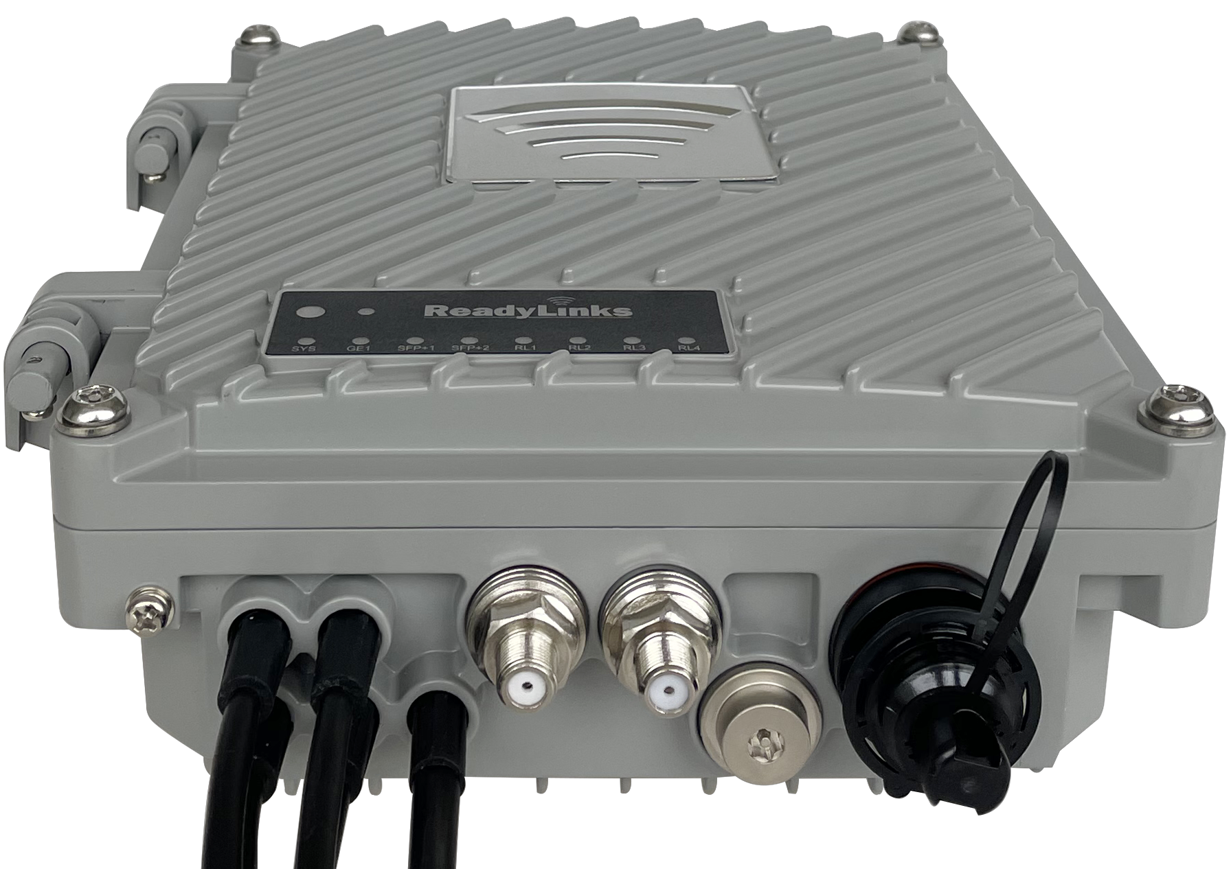
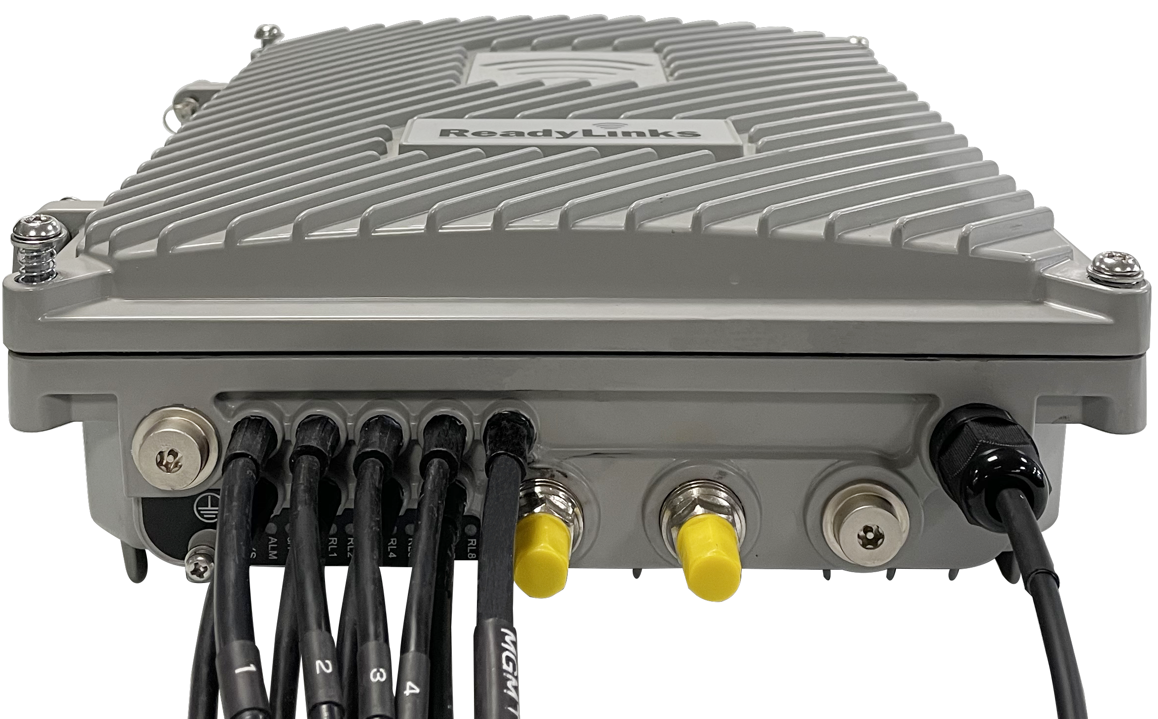
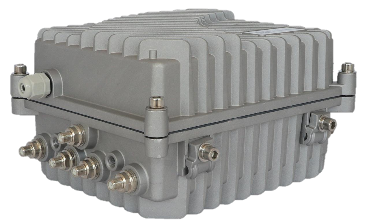
#Factory reset button
If the button is pressed and held for at least ten seconds and then released, the switch will reboot and be restored to its original factory settings by deleting all configuration information stored on the unit.
#Port and status LEDs
#GL-xTH-RPF series
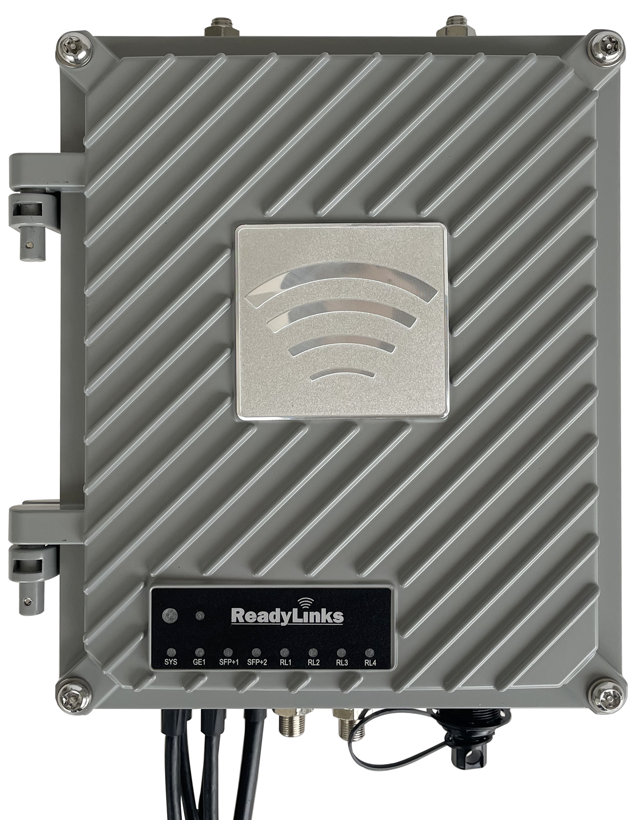
| Function | LED status | Meaning |
|---|---|---|
| ReadyView | 🔵 Blue | Your device is online and connected to ReadyView. It's good to go! |
| 🔴 Red | Your device is unable to find a way to the Internet. | |
| PWR | 🟠 Orange | Device is powering up or has fully booted. |
| ◯ Off | The device is off. | |
| GE1 | 🟢 Green | The MGMT copper tail is plugged into an active Ethernet port. |
| ◯ Off | The MGMT copper tail is unplugged or plugged into an inactive Ethernet port. | |
| SFP | 🟢 Green | An SFP is installed and the fiber link has been established. |
| ◯ Off | No fiber link. | |
| ReadyLink Port (RL) | 🟢 Green | The port is receiving power, and has established a data link. |
| 🔴 Red | The port is receiving power, but a data link has not been established. | |
| ◯ Off | The port is disconnected. |
#GL-xCH series
| Function | LED status | Meaning |
|---|---|---|
| PWR | 🟢 Green | Device is powering up or has fully booted. |
| System | 🟢 Green | The device is powered up and the system has fully booted. |
| ◯ Off | The device is still booting up. | |
| SFP | 🟢 Green | An SFP is installed and the fiber link has been established. |
| ◯ Off | No fiber link. | |
| ReadyLink Port | 🟢 Green | The port has established a data link. |
| ◯ Off | No data link has been established. |
#GL-xTH-RPF series (legacy, LEDs on the bottom)
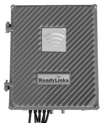
| Function | LED status | Meaning |
|---|---|---|
| PWR | 🔴 Red | Device is powering up or has fully booted. |
| System | 🟠 Orange | The device is powered up and the system has fully booted. |
| Alarm | 🔴 Red | There is an active alarm on the device. |
| SFP | 🟢 Green | There is an active SFP installed in the slot. |
| ◯ Off | No fiber link. | |
| ReadyLink Port | 🟠 Orange | The port is receiving power, and has established a data link. |
| 🔴 Red | The port is receiving power, but a data link has not been established. |
#GL-xTH-RPF series (legacy, LEDs inside)
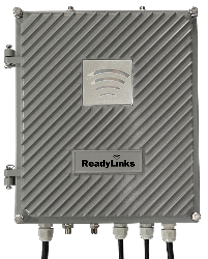
| Function | LED status | Meaning |
|---|---|---|
| PWR | 🟢 Green | Device is powering up or has fully booted. |
| System | 🟢 Green | The device is powered up and the system has fully booted. |
| SFP | 🟡 Yellow | There is an active SFP installed in the slot. |
| ◯ Off | No fiber link. | |
| ReadyLink Port | 🟢 Green | The port is receiving power, and has established a data link. |
| 🔴 Red | The port is receiving power, but a data link has not been established. |
#Package contents
- Wall mount bracket
- Mounting screws
- F sync cable
- Serial cable
#Pre-install preparation
You should complete the following steps before going on-site to perform an installation.
#Configure your dashboard network
- Log in to
https://ui.readylinks.io. If this is your first time, create a new account. - Claim your switches. You will need your ReadyLinks MAC address (found on the device), which looks like
0013xxxxxxxx. - Find the network to which you plan to add your switches or create a new network.
- Go to the map view and place each switch on the map by clicking and dragging it to the location where you plan to mount it.
#Check and configure firewall
If a firewall is in place, it must allow outgoing connections on particular ports to particular IP addresses. The most current list of outbound ports and IP addresses for your particular organization can be found on the firewall configuration page in your dashboard. See also firewall rules.
#Assign an IP address
All switches must be assigned routable IP addresses to be managed by ReadyView. These IP addresses can be dynamically assigned via DHCP or statically assigned.
#Dynamic assignment
When using DHCP, the DHCP server should be configured to assign a static IP address for each MAC address belonging to a ReadyLinks switch. Other features of the network, such as 802.1X authentication, may rely on the property that the switches have static IP addresses.
GL-24xT-P600D# configure terminal
GL-24xT-P600D(config)# interface vlan 10
GL-24xT-P600D(vlan-interface10)# ip address dhcp
GL-24xT-P600D(vlan-interface10)# end
GL-24xT-P600D(config)# vlan 10
GL-24xT-P600D(vlan10)# switchport tagged ethernet RJ45/G1
GL-24xT-P600D(vlan10)# end
GL-24xT-P600D(config)# management mode vlan 10
GL-24xT-P600D(config)# end
GL-24xT-P600D# show vlan int#Static assignment
Static IPs are assigned using the local web server on each switch. The following procedure describes how to set the static IP:
- Using a client machine (e.g., a laptop), connect to the switch over a wired connection.
- Using a web browser on the client machine, access the switch locally via serial.
- Enter the VLAN interface for management.
- Configure the static IP address, net mask, gateway IP address and DNS servers that this switch will use on its management connection.
- If necessary, reconnect the switch to the LAN.
GL-24xT-P600D# configure terminal
GL-24xT-P600D(config)# interface vlan 10
GL-24xT-P600D(vlan-interface10)# ip address 10.10.0.10 255.255.255.0 10.10.0.1
GL-24xT-P600D(vlan-interface10)# end
GL-24xT-P600D(config)# vlan 10
GL-24xT-P600D(vlan10)# switchport tagged ethernet RJ45/G1
GL-24xT-P600D(vlan10)# end
GL-24xT-P600D(config)# management mode vlan 10
GL-24xT-P600D(config)# end
GL-24xT-P600D# show vlan int#Removing the default interface
GL-24xT-P600D# configure terminal
GL-24xT-P600D(config)# interface vlan 1
GL-24xT-P600D(vlan-interface10)# no ip address#Installation instructions
#Wall mount
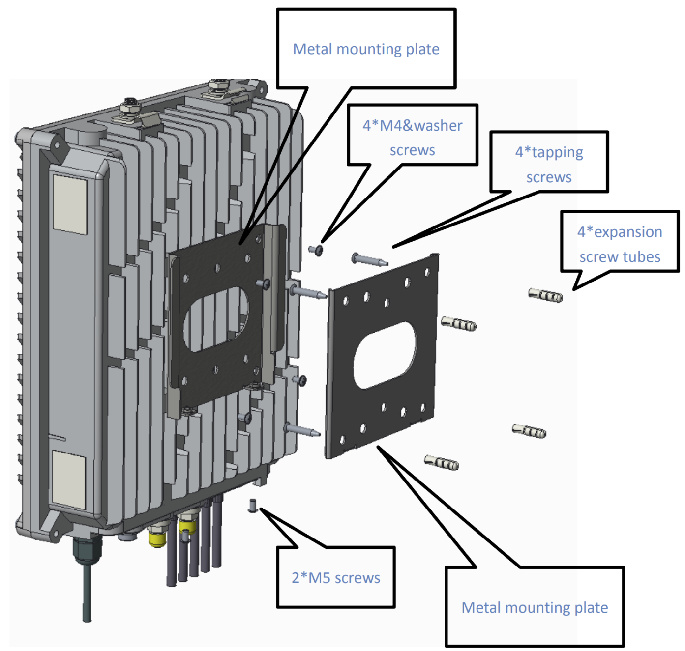
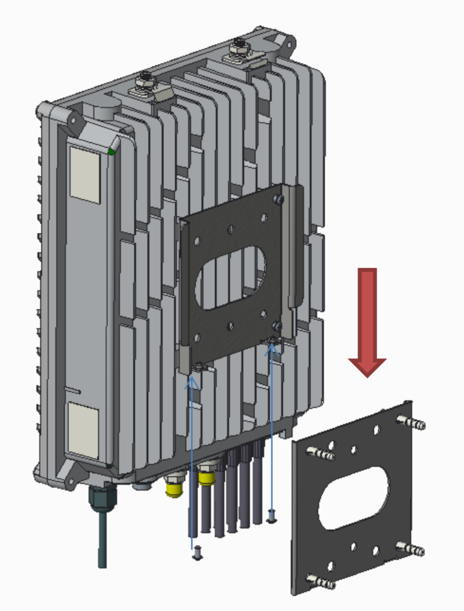
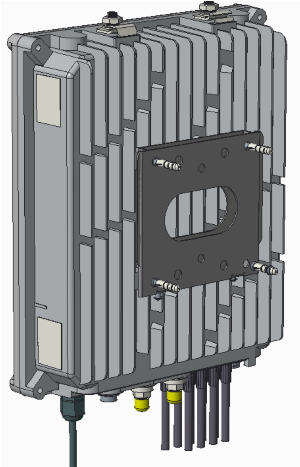
- Fix one side of the mounting plate on the wall.
- Fix the other plate on the back of the device.
- Slide the device over the mounting plate and install the security screw.
#Pedestal
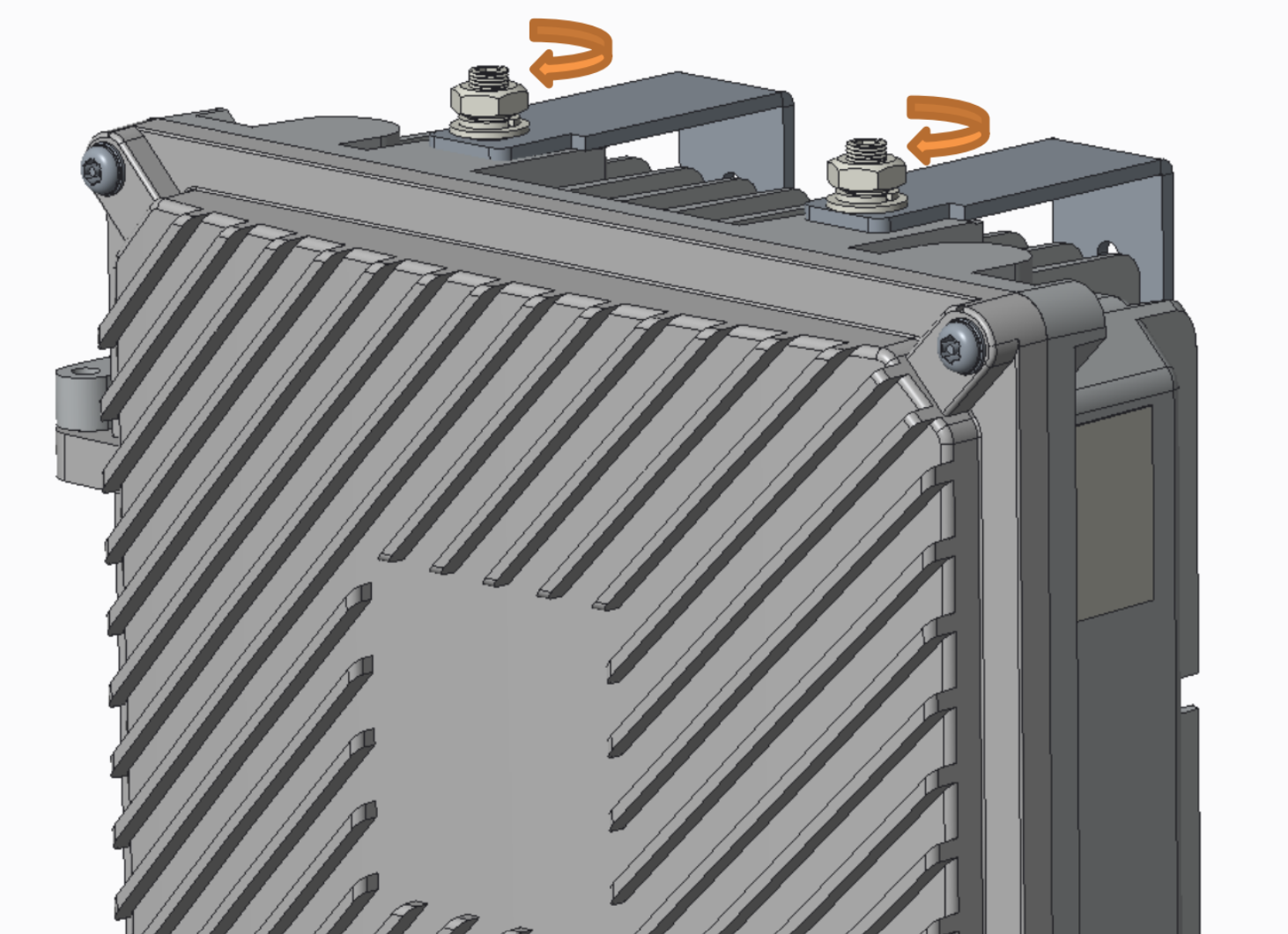
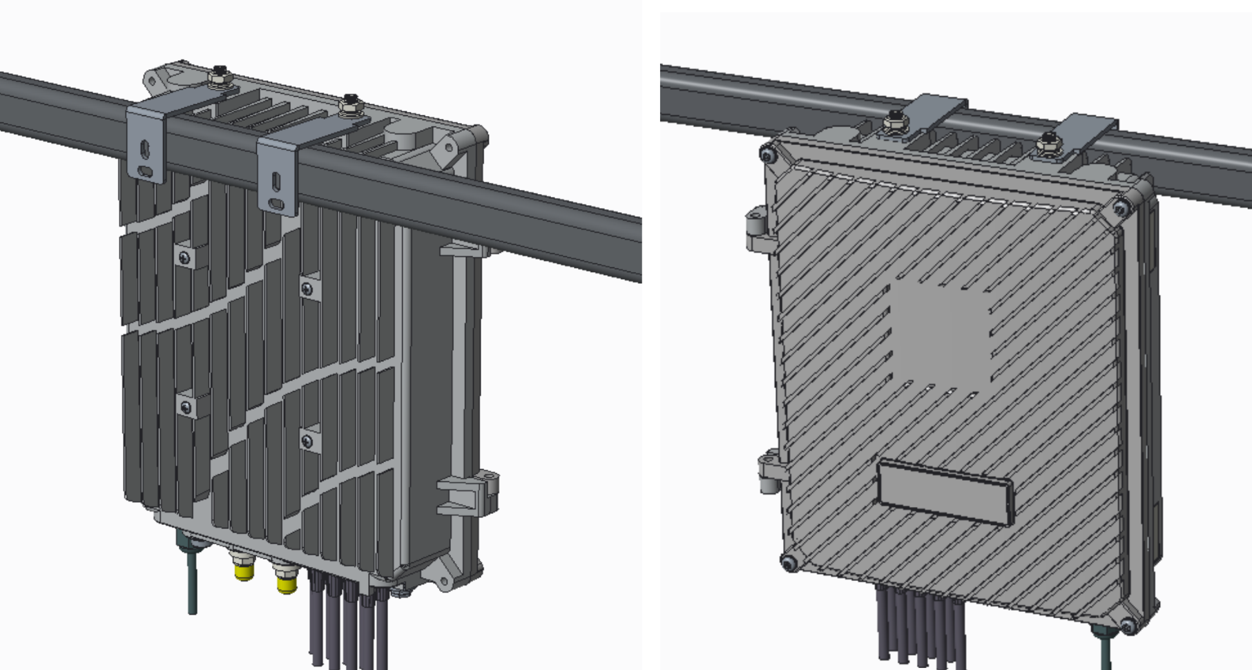
- Install the metal wings face down pointing toward the back of the device.
- Hang the unit on the internal crossbar of the pedestal.
#Aerial
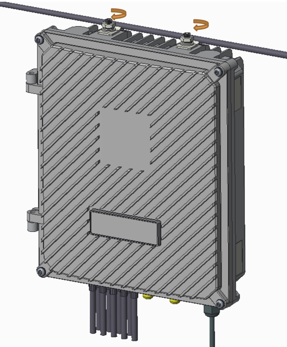
- Push the wire into the gap and hang the device on the wire.
- Tighten the two mounting nuts to secure the unit to the wire.
#Wiring instructions
Refer to the twisted pair or coax sections of the wiring instructions guide for details on how to connect your ReadyLink devices.
#Mounting hardware
The mounting hardware includes a wall mount kit for standard backboards, dry wall, and building siding. When installing the device, make sure that there is sufficient space around the device to support an adequate fiber bend radius.
#Basic troubleshooting
The following steps can be used for troubleshooting basic connectivity issues with your switch.
- Reset the switch
- Factory reset the switch by holding the factory reset button for 10 seconds
- Try switching cables, or testing your cable on another device
#Warranty
#Warranties, returns (RMAs)
ReadyLinks Inc. products come with a default 1 Year Hardware Warranty against defects in materials and workmanship when used normally. Causes of performance issues that are beyond the reasonable control of Supplier or excluded under the ReadyLinks limited warranty are not included in the scope of the warranty. If your ReadyLinks device fails and the problem cannot be resolved by on-site troubleshooting, contact Partner for troubleshooting assistance. Once Partner determines that the device hardware is in a failed state, they can process an RMA and send out a replacement device. In most circumstances, the RMA will include a pre-paid shipping label so the faulty equipment can be returned.
#Returns (RMA) limitations
RMAs may only be requested by Client Administrators (Read Only or Full Access to Core Services). Supplier will not process RMAs unless the Partner can verify the Client has sufficient network permissions. Non-cancellable orders are not eligible for RMA credit and are not eligible for an RMA exception.
#Additional resources
- Switching: GLx series, GLxH series, Ethernet series, Configuration templates
- Other: Best practices, Installation guides, Developers
Last updated May 2, 2023