Topology and racks
See how a site's switches, access points, and clients connect, trace a device's route to the gateway, replay past topology changes, and lay out devices in racks.
The Topology page draws the site's network as a graph built from LLDP: which device is connected to which, and on which ports. The Infrastructure page shows the same devices mounted in their racks. Open either one from Network in a site's left rail, or switch between them with Graph and Racks at the top of the page.
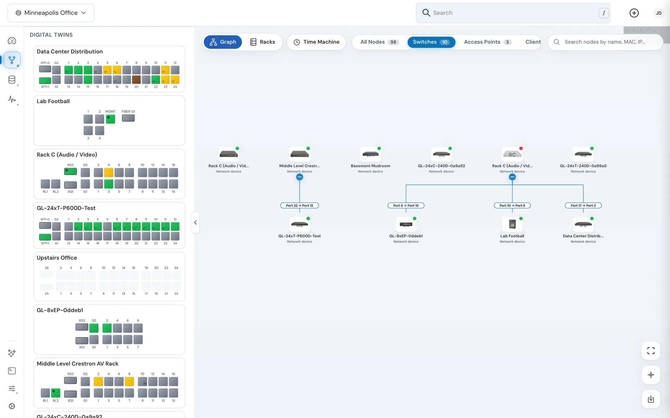
#Read the graph
Each device is a card with its picture, name, and type, and a status dot. Lines between cards are links, labelled with the ports at each end (for example Port 3 → Port 24). Hover a label to see both device names and ports, with "(from LLDP)".
- A circle below a card collapses or expands the devices under it. A collapsed card shows how many devices it hides.
- Show connected devices on a card adds the end devices connected to it. Hide connected devices removes them again.
- Click a card to open that device's panel. See Switch, access point, and client details.
If the graph is empty, the page says "Enable LLDP for this network to generate a network topology." Turn on LLDP on the site's switches; see Switch settings.
#Filter and search
The chips above the graph show a count each:
| Chip | Shows |
|---|---|
| All Nodes | Every device |
| Switches | Switches |
| Access Points | Access points |
| Clients | Clients |
| Offline / Degraded | Devices that are offline or degraded. Shown only when there are some. |
| LAG Links | Redundant and aggregated links. Shown only when there are some. |
Type in Search nodes by name, MAC, IP... and click a result to jump to that device.
#Move around the graph
The buttons at the bottom right are Fit to screen, Center graph, and Download topology export, which saves the graph as a PDF.
#Digital Twins
In Graph view, the Digital Twins panel on the left shows a live front panel for each switch, with port lights for link and PoE.
- Hover a twin to highlight that switch on the graph.
- Click a twin to open the switch's panel.
- Click Load more at the bottom to show more switches.
Click the arrow on the panel's edge to collapse it and give the graph more room.
#Trace a route to the gateway
- Hover a device's card and click the arrow button that appears on its right.
- The graph highlights the path from that device (Origin) to the Gateway, with the number of hops. A badge says Route Healthy or Route Issues.
- Click Route Details to list every hop with its IP and MAC address. Click a hop to select it on the graph.
- Click Clear to remove the trace.
#Look back with Time Machine
Time Machine replays changes to the site's network: devices added and removed, devices going offline and coming back, and links added, removed, or moved.
- In Graph view, click Time Machine. A panel opens on the left.
- Choose a time range: 1H, 24H, 7D, or 30D.
- Turn change types on or off: Device added, Device removed, Status, Link added, Link removed, and Link moved.
- Drag the timeline, or click a change in the list, to view the network at that moment. A banner reads Viewing topology as of the time you picked.
- Click Return to live to go back to the current network.
While you're viewing the past:
- Devices and links that weren't there yet are hidden.
- Devices and links that existed then but are gone now are drawn faded and dashed. You can't open them.
- Every device shows its status as it was then.
- End clients are hidden, and the banner says how many.
History starts when ReadyView began recording it for the site. Before that, the page says there's no topology history and shows the live network.
Ports Manager has its own Time Machine for one switch's ports.
#Racks
Racks (or Infrastructure in the rail) shows the site's devices in their racks, built from the IDF and rack groups on the site's floor plans.
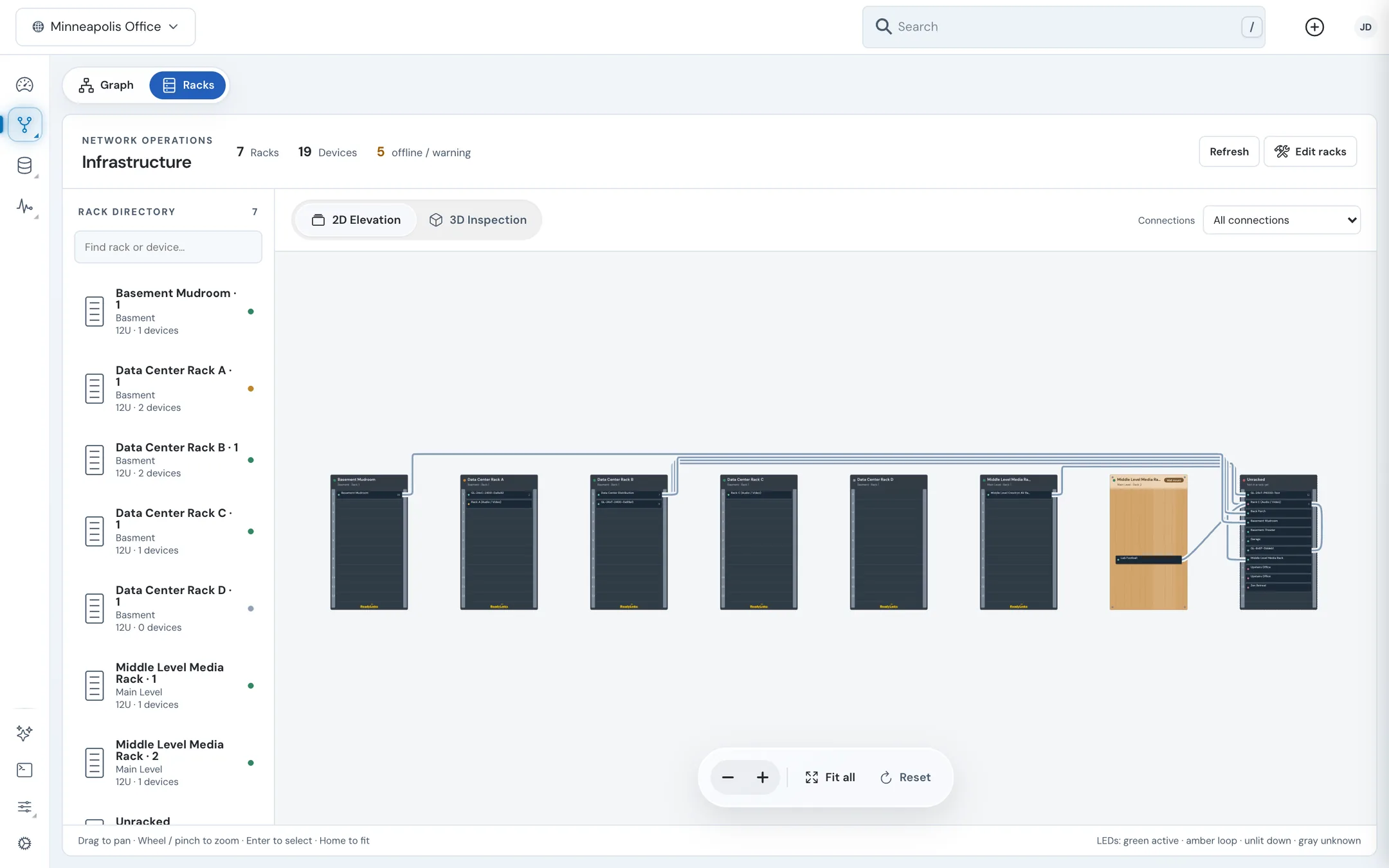
The header counts Racks, Devices, and devices that are offline / warning. Refresh reloads the layout.
#Find a rack
The Rack directory on the left lists every rack with its floor plan, height in rack units, and number of devices. Type in Find rack or device… to filter it, then click a rack to go to it. Unracked collects devices that aren't in a rack yet.
#Choose a view
| View | What you see | Move around |
|---|---|---|
| 2D Elevation | Every rack face-on, side by side, with cable paths between devices | Drag to pan, wheel or pinch to zoom, Enter to select, Home to fit |
| 3D Inspection | The racks as a 3D model | Drag to orbit, right-drag to pan, wheel or pinch to zoom |
The canvas has Zoom out, Zoom in, Fit all, and Reset buttons. Port LEDs follow the legend in the footer: green active, amber loop, unlit down, grey unknown.
Use Connections to choose which cables to draw: All connections, Selected rack / device, Selected connection (2D), or Hidden. A Critical uplink is a single cable that, if cut, takes devices offline. Redundant and LAG links are drawn differently.
#Inspect a device or cable
Click a device in a rack. The bar at the bottom shows its name and model, with:
- Open device: opens the device's panel.
- Inspect ports: pick a port to see its link status.
- Impact: shows what fails with this device, for example "If this device fails, 3 downstream devices lose their path to the core." Devices that stay up through a redundant link are counted separately.
Click a cable to see the devices at each end, whether it's a critical uplink, and how many devices are downstream of it.
#Edit racks
Editing racks changes the site's floor plans, so Edit racks appears only if your role can edit floor plans.
- Click Edit racks. The view switches to 3D Inspection.
- Drag devices between rack slots, or from Unracked into a rack.
- Select a rack to change how it's built (Rack or Wall mount), rename its IDF, or add and remove racks.
- Use Add rack to add a rack to an IDF, or Add IDF to create a new IDF here without going to Floor Plans. Give the IDF a Name and choose its Floor plan. If the site has no floor plan yet, one is created for it.
- Press Esc or click Done when you're finished.
A few rules apply:
- Only an empty rack can be removed, and only the last rack of an IDF. An IDF keeps at least one rack; delete the IDF instead.
- Delete IDF removes its racks, and their devices become unracked.
- Devices can only move between racks on the same floor plan.
If a change can't be saved, it's undone and a message says so.
To place IDFs on a plan and set rack units there, see Floor plans.
#Related guides
Last updated November 10, 2026