Precision Time Protocol (PTP)
How ReadyLinks carries IEEE 1588v2 Precision Time Protocol across G.hn coax as a two-step transparent clock, what the grandmaster and slaves need, how to size a coax drop, and how to verify and troubleshoot it.
Some devices need more than the right time of day. Small-cell radios, private 5G and LTE gear, some Wi-Fi access points, and audio or video systems need their clocks aligned to within microseconds or better. Precision Time Protocol (PTP), defined in IEEE 1588v2, does this over an ordinary packet network. A grandmaster clock sends timing messages, and each slave uses them to measure its offset and the path delay, then steers its own clock.
PTP works best when every hop has a fixed, small delay. G.hn over coax does not: frames wait for their slot on a shared medium, so the delay changes from packet to packet. ReadyLinks G.hn nodes solve this by acting as a transparent clock. They measure how long each PTP message spends crossing the G.hn segment and write that time into the message, so the slave can subtract it.
This page covers what is supported, how it works, what the grandmaster and slaves need, how to size a coax drop, and how to verify and troubleshoot a deployment.
#What ReadyLinks supports
| Function | Supported | Notes |
|---|---|---|
| End-to-end (E2E) two-step transparent clock on G.hn | Yes | On G.hn coax segments, with the PTP-enabled G.hn firmware |
| Two-step grandmaster | Required | The grandmaster must send Follow_Up messages |
| One-step grandmaster | No | Delay_Resp is still corrected, but no Follow_Up is generated, so accuracy drops sharply |
| Grandmaster, boundary clock, or ordinary clock on a ReadyLinks switch | No | Use a dedicated grandmaster and a PTP-capable slave |
| Transparent clock on switch Ethernet ports | No | Ethernet ports forward PTP frames as ordinary multicast / Layer 2 traffic |
A transparent clock does not remove delay or jitter. It reports the delay each message picked up so the slave can correct for it. The slave must run a real PTP servo that uses the correctionField, for example ptp4l from linuxptp.
#How it works
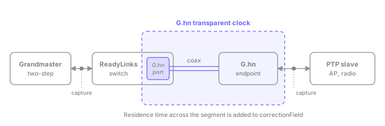
Every PTP message carries an 8-byte correctionField. A transparent clock adds its residence time — the time the message spent inside it — to that field. The slave subtracts the total correction from its delay calculation, so the variable G.hn delay drops out.
In a two-step exchange the timestamps travel in a second message, so the G.hn nodes correct the follow-up message, not the original:
- Sync is timed on its way through the G.hn segment, but not changed.
- Follow_Up gets the residence time of its matching Sync added to its correctionField.
- Delay_Req is timed on its way back through the segment, but not changed.
- Delay_Resp gets the residence time of its matching Delay_Req added to its correctionField.
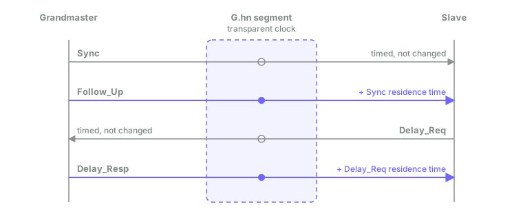
This is why a two-step grandmaster is required. If the grandmaster is one-step, there is no Follow_Up for the G.hn nodes to correct, and the Sync residence time is lost.
#Requirements checklist
- PTP-enabled G.hn firmware on every G.hn node in the domain.
- Transparent clock enabled on all G.hn nodes — the head-end G.hn port and every endpoint. One node left out breaks the correction.
- A two-step grandmaster. The
twoStepFlagmust be set and the grandmaster must send Follow_Up. - End-to-end delay mechanism (Delay_Req / Delay_Resp).
- Slaves with a real PTP servo that applies the correctionField, such as
ptp4l. - Low G.hn latency on the coax drop. See sizing.
- Multicast snooping off on the G.hn domain (IGMP and MLD on the G.hn nodes).
#Enabling the transparent clock
ReadyLinks support enables PTP transparent clock per deployment. The settings below are applied on the G.hn nodes, not through the switch CLI. They are listed for reference so you know what to expect. Most take effect only after the node reboots.
| Parameter | Value | Purpose |
|---|---|---|
PTP.GENERAL.ENABLE | YES | Turns on PTP handling on the node |
PTP.GENERAL.TRANSPARENT_CLOCK | YES | Turns on transparent clock mode |
PTP.GENERAL.SLAVE_ONLY | YES | Keeps the node from trying to become a PTP master |
PTP.GENERAL.PORT | 0 or 1 | Endpoint Ethernet port that faces the PTP device (0 = port A, 1 = port B) |
Recommended extra settings on point-to-multipoint coax:
| Parameter | Value | Why |
|---|---|---|
QOS.SCHED.TRAFFIC_AWARE_ENABLE | NO | Stops the link moving between idle and active states, which adds delay |
MCAST.GENERAL.IGMP_ENABLE | NO | PTP uses multicast; IGMP snooping on the G.hn nodes can interfere with it |
MCAST.GENERAL.MLD_ENABLE | NO | Same reason, for IPv6 multicast |
RTM.GENERAL.UNKNOWN_SUPPRESSION | NO | Keeps PTP frames from being suppressed as unknown traffic |
#Sizing a coax drop
On point-to-multipoint coax, the head-end G.hn port has a fixed budget for PTP messages. In testing, about 32 PTP packets per second in total per coax port synced reliably. Above that, slaves lost sync. Split the budget across the slaves on that port:
| Slaves on the coax port | PTP rate per slave |
|---|---|
| 1 | 32 packets/s |
| 2 | 16 packets/s |
| 4 | 8 packets/s |
| 8 | 4 packets/s |
A rate of 4 packets per second per slave tested good. Rows above two slaves are budget math; size them with ReadyLinks engineering.
Latency matters as much as rate. G.hn latency grows with the number of endpoints on the line:
| G.hn latency | Result |
|---|---|
| Under 2 ms | Recommended for stable sync |
| About 10 ms average (16 endpoints on the line) | Challenging |
| 5 to 10 ms residence time (heavily loaded line) | Too high; expect unstable sync |
Design guidance:
- Keep few endpoints per PTP coax drop.
- Use low sync rates that fit inside the per-port budget.
- Turn multicast snooping off on the G.hn domain.
- The reference design that was validated end to end is one head-end port with two endpoints. Size larger domains with ReadyLinks engineering.
#Verifying sync
#On the slave
With linuxptp, run the slave in end-to-end mode and watch the output:
ptp4l -i eth0 -s -E -mUse the same transport as your grandmaster. When the slave is locked, the servo state is s2 and the master offset values stay small and steady. If the offset keeps growing or the state falls back to s0, see troubleshooting.
#With packet captures
Take two captures at the same time:
- On the Ethernet side before the head-end G.hn port (between the grandmaster and the switch).
- On the Ethernet side after the endpoint (between the endpoint and the slave).
Compare the correctionField of the same Follow_Up and Delay_Resp in both captures. The value after the segment should be larger by the residence time. A residence time of 0 means that packet has not crossed the transparent clock.
Do not capture in the middle of the G.hn segment. Frames there carry 4 extra bytes and show an invalid FCS.
#On the G.hn node
ReadyLinks support may read these from the G.hn node console:
PTP.STATS.PACKETS— per-type counters for PTP messages sent and received (Sync, Follow_Up, Delay_Req, Delay_Resp, Announce, and others).PTP.STATS.PACKETS_RESET=YES— clears the counters before a test.
For a detailed trace, support sets SYSLOG.OUTPUT.MODE=console, reboots the node, then starts the PTP trace with /syslog l ptp + a and stops it with /syslog l ptp - a.
#Troubleshooting
| Symptom | Likely cause | Fix |
|---|---|---|
| Slaves never lock | Grandmaster is one-step | Switch the grandmaster to two-step (twoStepFlag set, Follow_Up sent) |
| Slaves lock, then lose sync as more are added | Head-end PTP budget exceeded | Lower the sync rate per slave so the port total stays near 32 packets/s |
| Offset wanders, large path delay jumps | G.hn latency too high on the drop | Reduce endpoints on the drop; target under 2 ms latency |
| Offset matches the raw G.hn delay | One or more G.hn nodes not running the transparent clock | Check PTP settings and firmware on every node, then reboot |
| Erratic PTP delivery to some slaves | Multicast snooping on the G.hn nodes | Turn IGMP and MLD snooping off on the G.hn domain |
| Correction looks right but slave is still off | Slave ignores correctionField | Use a PTP servo that applies it, such as ptp4l |
| "Invalid FCS" on PTP frames in a capture | Capture taken inside the G.hn segment | Capture before the G.hn ingress and after the egress |
| correctionField residence time is 0 | Packet has not crossed the transparent clock | Check the capture point and that the node has PTP enabled |
#FAQ
Does the transparent clock reduce jitter? No. It measures the delay each message picks up and reports it in the correctionField. The slave's servo uses that to compensate.
Can a ReadyLinks switch be the grandmaster or a boundary clock? No. Use a dedicated PTP grandmaster. ReadyLinks switches forward PTP on Ethernet ports as normal traffic and correct it only on G.hn segments.
Does it work with a one-step grandmaster? Not well. Delay_Resp is still corrected, but there is no Follow_Up to carry the Sync correction. In testing, slaves did not lock until the grandmaster was switched to two-step.
Does it work on phoneline? The transparent clock is documented and tested on G.hn coax. Contact ReadyLinks before planning PTP over a phoneline G.hn segment.
What sync rate should I use? Start low. 4 packets per second per slave tested good. Keep the total across all slaves on one coax port at or below about 32 packets per second.
How many endpoints can share a PTP coax drop? As few as practical. The validated reference is one head-end port with two endpoints. Size anything larger with ReadyLinks engineering.
I see "PTP" in a G.hn profile name. Is that this feature? Not necessarily. In some G.hn profile names, PTP means point-to-point (one endpoint per coax drop), not Precision Time Protocol.
How do I turn it on? Contact ReadyLinks support. Transparent clock needs the PTP-enabled G.hn firmware and the settings above on every node.
#Related
- Multicast — group addresses and snooping, which PTP relies on.
- Switching and VLANs — how PTP frames are forwarded across the switch.
- Glossary — short definitions of the terms used here.
Last updated October 25, 2026